TL;DR: This creates a cape for the BeagleBone Black using readily available replacement spare TFT Panels and a capacitive touchscreen originally found in cheap tablets.
[ You can also follow the project at Hackaday.io ]
Thanks to the economy of scale, the market of lower-end tablets is flooded with N brands available at almost throwaway prices. Here one can buy a cheap one for less than ₹3000 ($45) and get a decent 7″ screen with capacitive touch. But when it comes to the BeagleBone Black I either saw that most of touch screens available were resistive and panels with capacitive screens were out of my budget, especially when you know you could leveraging the same economy of scale build one 🙂 . I decided to take on the challenge and build a cape for the BeagleBone out of these readily available parts.
This December during my winter break at Jakarta, I shopped at Glodok and Roxy – the electronics and mobile spare part shopping hubs respectively [compare that to HQB, Shenzhen but at a smaller scale though]. What really caught my attention was 7″ TFT panels and capacitive touch digitizers in shops – the LCDs looked very close to the cheap 7″ LCD panels being sold on eBay and other places with a Realtek-based HDMI converter which I wanted to check out lately (like this).
These panels are known by the name AT070TN9x (x=0,2,3,4) and are originally manufactured by Innolux and have 50-pin connectors with a TTL interface (datasheet here). But were the panels being sold in the markets the same AT070TN92 panels, their clones or something different? I decided to find out and requested at the shops to be able take a photo of a few models of these. Got home and tried to match the pinout on the panel with the AT070TN92. Bingo. Perfect match for almost every one of them. Even though the panels have slight dimensional differences in the bezel, they have the same pin layout and should (hopefully) be the same from the inside.

Here you can see the one which has KR070PM7T written on it. The giveaways – Pins 1 & 2 (VLED+) shorted, 3 & 4 (VLED-) shorted. Pins 45, 49 and 50 are not connected. If you refer the datasheets, the pin definitions seem to align.
I bought two panels and mix-matched them with available capacitive touch panels to see which one fitted the screen the best. I also bought from a nearby shop the ZIF FPC connectors for the display and the touchscreen. The display one is 50 pins, 0.5mm pitch and the touch panel has 6 pins at a 0.5mm pitch. Not exactly breadboard friendly but very PCB friendly. As seen on the image at the top of the post (not this one) the LCD is sitting over the capacitive touch panel and you can see the 6-pin connections there. No reverse engineering needed for the capacitive touch FPC as the connections for the 6 pins are already highlighted in the image!
Okay, now I had to find a good driver for the LCD. I was aware of the TI TFP401 DVI (HDMI) receiver and could get samples if I wanted. But hey, the BeagleBone converts from TTL to HDMI and then I’m gonna convert HDMI to TTL, right? Why not just cut through the layers and wire the display directly? Should just be D0-D15, VSYNC, HSYNC, PCLK, 3V3, backlight, adjust LCD driver resolution, timings and done. Turns out we’re not done, yet.
The catch
Every LCD requires a high voltage to control the twist of individual liquid crystals. This voltage is usually internally generated using charge pumps but turns out that this “dirty” LCD panel ( DirtyPCBs 😛 ) expects the voltages to be supplied externally to it. The LCD expects approximately 10.4V for AVDD, 16V for VGH and -7V for VGL to be supplied to it. Hmm, how do I generate these?
The answer was not very hard to find. I was able to get Allwinner’s A13 based reference design for tablets that use a display (no points for guessing which one) with a 50 pin interface. Looking at their gate voltage generation circuits, we get this:

This app note from Maxim Integrated explains what we’re looking at [scroll down to the end of the appnote]. The AVDD rail draws the maximum current so it gets powered it by the boost converter. Then the diode and the capacitors form a charge pump generating approximately +21 V and -10.4 V from that rail and the Zener regulates it down to the needed voltages. Very cool.
I’ve ordered some boost converters from AliExpress, the ones called SY7201 and XR1151 which are as of now stuck in the Chinese New Year holiday shutdown. Until then I would test with a TPS61061 which I have at hand.
The design
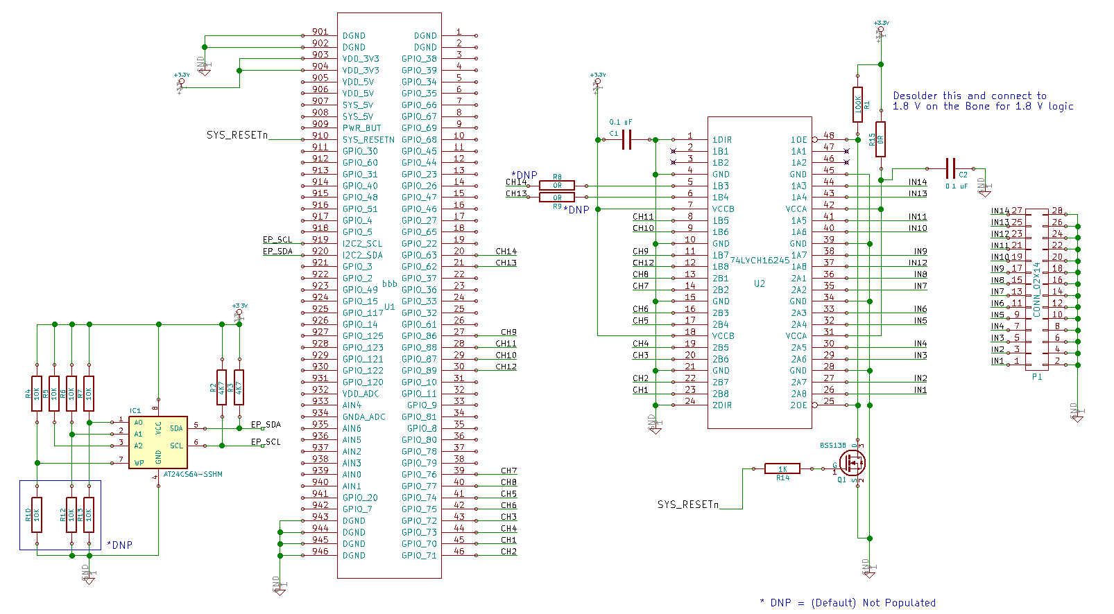
The schematic of a beta cape is almost done and I’m proceeding with routing of the PCB as at the time of writing. Here’s a peek on how the schematic looks right now, the final will be different from this one:

The beta version is to be a locally fabricated quick turnaround prototype so that I get something to work up the software side until the PCB for the first batch is manufactured. The production cape may include termination resistors or a 74LVC322245 buffer.
The capacitive touch side is simple. Two I2C pins and an interrupt pin to inform of touches. Turns out that the LCD uses only 47 out of the 50 signals and I can squeeze these three lines into the same FPC as the display using an extension cable and adapter PCB. So I’ve done it this way as can be seen above. The Linux kernel already contains a driver for the ft5x06 in drivers/input/touchscreen/edt_ft5x06.c . So getting the touch for the LCD should just be equivalent to writing some device tree code to invoke the module.
That was a long post. The next posts would feature testing of the capacitive touch panel and of the prototype.