The STM32F4Discovery from STMicroelectronics is one of the mature, extremely affordable, and yet capable development boards available in the market [I say mature because it has been around for quite a while; since Q4 2011]. The board is equipped with a STM32F407VGT6 ARM Cortex-M4 Core with embedded FPU running at 168 MHz, 1 MB of Flash and 192 KB of SRAM, and adds an accelerometer, a CS43L22 Stereo Audio DAC (with a headphone jack), an MEMS digital microphone and USB OTG support. The demos provided by ST demonstrate its audio playback and recording capabilities, which I was quite impressed with when I tested it for the first time.
The STM32F407 Microcontroller also packs in support for seamless LCD interfacing (via FSMC), SDIO, DCMI and Ethernet, hence I built a circuit to augment the STM32F4Discovery board capabilities by adding support for attachment of:
- TFT LCD module with a touchscreen. These are cheaply available via eBay.
- a microSD card [power to the card controllable via a PMOS switch].
- Camera module with a 8-bit HSYNC/VSYNC/PCLK interface.
- [Planned] Ethernet support, either via ENC28J60 or a DP83848 Ethernet PHY
The circuit was initially wired in Summer 2013 and recently modified to support audio playback alongside SDIO [see article here]
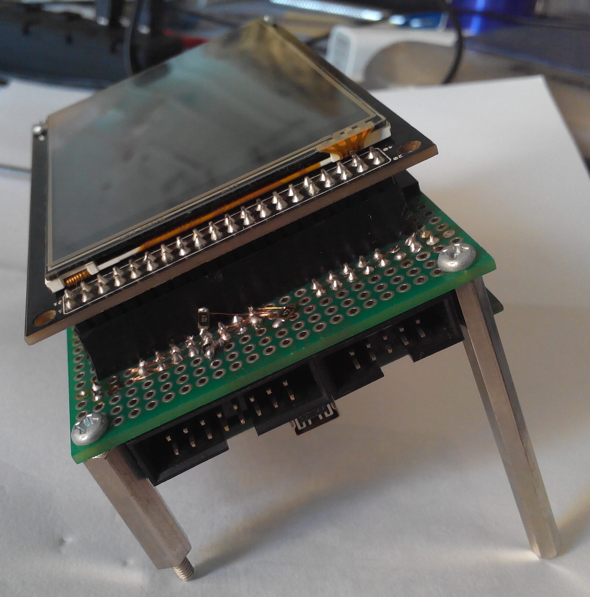
Here’s a pic of the board up and running:

Hardware
A double sided PTH dot matrix board is used for construction. The board was just in size to accomodate the STM32F4Discovery board on one side and the LCD with its 40-pin connector on the other making it a stacked 3-layer design. 0.1mm Magnet wire is used for all electrical connections.
The LCD side also has a 3.3V LDO for power distribution, a connector and charging circuit for a 1-cell Li-Ion battery. It also has a connector for a 10-DOF IMU for expansion.
Two 2.5cm spacers and two 6 cm metal studs mounted on the 4 mounting holes on the PCB act as an inclined stand for the assembly to be kept on a table top.


LCD
The LCD used is a 3.5″ HVGA LCD display [320×480 pixels] with a 4-wire touchscreen, mounted on a breakout board. The module used in it is a TRULY TFT1P7134-E, which uses HFFS (High Fringe Field Switching) technology, which is somewhat similar to In-Plane switching (IPS) and gives true-to-life colors. There is no color distortion noticed in the image, even when viewed at almost 180degree angles from any direction. It uses the Renesas R61581 TFT controller, which is an enhancement of the ILITek ILI9481 originally used in such displays (the instruction set is nearly compatible).

It connects to the 16-bit FSMC bus on the STM32F407 Microcontroller, which allows the LCD to be accessible as simply external memory, and enables DMA usage for data transfer to save CPU utilization. The module reset pin is connected to the MCU reset pin. The backlight is connected through a PMOS to TIM5 on the STM32F407. The R61581 supports in built LED backlight control, but I have disabled it and gone for the direct control in order to support more compatible displays.
The LCD breakout board contains a XPT2046 (ADS7846 compatible) touchscreen controller that interfaces the 4-wire touch panel via the SPI bus to the microcontroller. The PENIRQ output provides feedback on screen touch.
Almost any LCD from eBay which comes with a 40-pin connector will be able to connect to this connector and can be supported with suitable changes to firmware.
The uGFX library is used to interface to the LCD and touchscreen. It also provides a widget toolkit for UI design. The R61581/ILI9481 drivers adapted for this board have been contributed by me to the uGFX project.
microSD Card

FatFS is used on the software side for file operations on the card. Read speeds of up to 9MB/s (theoretical maximum is 12MB/s) have been achieved with large buffer sizes.
Card detection is currently not implemented, but will be taken care of in future hardware revisions.
Camera Module
The STM32F407 contains a Digital Camera Interface (DCMI) bus that captures data sent in by a digital camera in the 8-bit format with external/inframe synchronization. Here only the HW synchronization via HSYNC/VSYNC/PCLK is used. The connector on the board was designed to be compatible with a OV7670 camera module, like the one available here
To drive the camera module, the XCLK is fed from PA8, which is a master clock output of the STM32F407. The MCO1 is configured to output a 16MHz clock using the HSI.
The control bus for the camera is SCCB, which does work with standard 400kHz I2C signals, with modifications in the way data is read, and delay between subsequent transfers.
I did try interfacing with a OV7670 camera module but I was largely dissatisfied with the results, they were terribly off-color.
IMU

Software
The board runs ChibiOS and uGFX.
ChibiOS is different from many other real time kernels in the fact that it offers a tightly integrated hardware abstraction layer (HAL), which is very well written and easy to use. The HAL provides, among other things, off-the-shelf support for SD cards via both SDIO and SPI and integration with the FatFS library, GPIO configuration and asynchronous transfers on SPI and I2C and serial ports, with built-in support for DMA usage to offload transfers and save the CPU for computation. ChibiOS 2.6.3 is currently being used.
uGFX offers support for rich graphics and touch input. It also offers a GUI toolkit which can be used with a Windows/Linux simulator to develop GUI on embedded devices.
Both ChibiOS and uGFX are available under a dual license for free non-commercial usage and commercial licenses once used in production purposes.
A custom board file was created off the reference STM32F4Discovery board.h and board.c .
Drivers have been written for the CS43L22 using the ChibiOS STM32 HAL. Since I2S support is currently not implemented in the STM32 HAL, I had to implement I2S configuration & circular transfer using DMA.
The software development takes place using an Eclipse-based development environment on Windows 8, with GNU Tools for ARM Embedded Processors . OpenOCD is used to debug in-circuit using the onboard ST-LINK/V2.
This summarizes the complete development platform.
Schematics would be coming soon.